Breaking Down Parts Into Sub-Parts
Once the machine is broken down into individual parts, then those parts can be further broken down into sub-parts.
Going back to the simplified part breakdown of a 3D printer as an example:
Frame
X, Y, and Z Axes
Extruder
Heated Bed
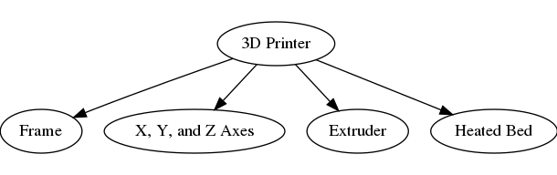
Simplified part breakdown of a 3D printer
We may breakdown the Frame into:
Angled Bars
Angled Bar Connectors
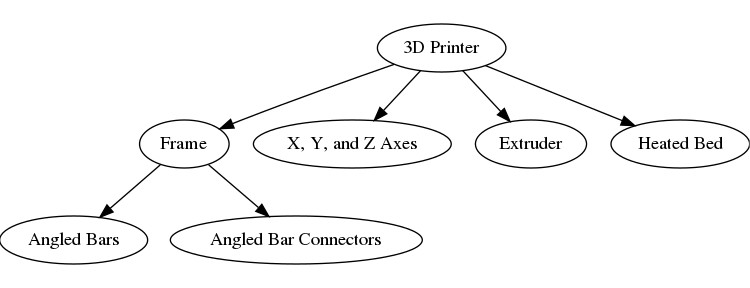
Further part breakdown of a 3D printer with Frame breakdown
Terminology
The amalgamation of parts and sub-parts is called an assembly.
Also note, there may not be a difference between a part and a sub-part.
The “part” and “sub-part” terms are contextual.
For example, the Frame is both a part in it’s own right, and a sub-part of the 3D printer.
Level of Breakdown
Similarly, we could breakdown the axes, extruder, and heated bed into sub-parts.
Then, we could continue breaking down those sub-parts into sub-parts until we get to the most basic parts of the machine.
There’s no real limit to how far you can breakdown a machine. It’s recommneded to continue breaking down a machine for as long as it’s useful and practical.
Tip
See Depth of Modularity for more information.
Similar guidance as specified in breaking down a machine applies.
For the first iteration of a workbench, it’s easier to include less detail in the breakdown of parts.
File size, memory consumption, and performance must also be considered when designing a workbench.
For example, parts that include more details will take up more space on disk, take longer to render, and potentially slow down FreeCAD.
Due to these limitations, starting with simplified parts is recommneded.
3D Printing Considerations
Does the part need to be 3D printed?
If so, then you’ll need to include all details in the part.
In cases like this, it’s helpful to allow the user to create a simplified version of the part for modeling purposes, and the full-detailed part separately for exporting to STL or OBJ for printing.
Next Step
Once the top-level parts are broken down into sub-parts, those parts can be designed in FreeCAD.