Designing Parts
Once the machine is broken down into individual parts, and those parts are broken down into sub-parts, then someone can design those parts in FreeCAD.
The generated FreeCAD asset files for each part can be documented on the OSE Wiki as a Part Library.
The Part Library serves as a helpful guide for developers who need to replicate that geometry programatically in Python.
Design All the Variations
Does the part have different states or variations?
For example, the Angle Frame Connector, or part that connects the angled bars together for the 3D Printer Frame, can include extra geometry for holding the angled bars in place with a set screw.
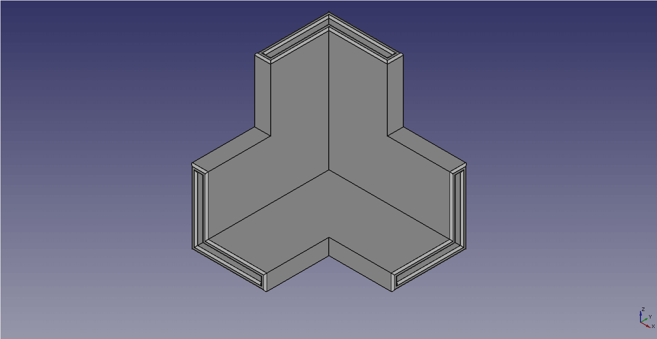
Angle Frame Connector
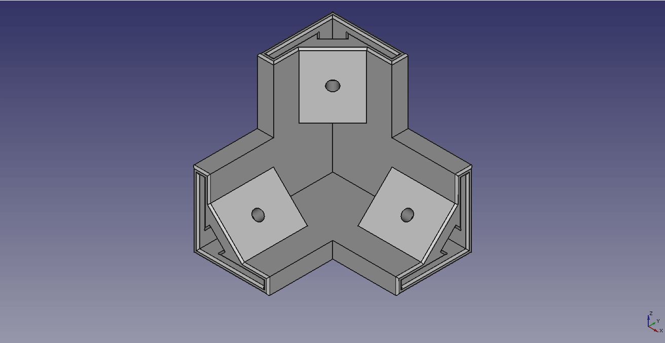
Angle Frame Connector with Set Screw
Note, the basic geometry in both designs are very similar.
The design with a set screw is a more complicated variation of the initial design.
A developer can take advantage of this similarity to reduce and share code when developing the part in the workbench.
It’s easier to identifiy variations up-front in the design phase before writing the code.
Define the Parameteric Properties
What are the parameteric properties?
What attributes of the part do you want to parameterize, or allow the user to change and input values for?
For example, the Angle Frame Connector can have different slot widths and thicknesses to support smaller or larger 3D Printer Frames.
Below we see two angle frame connectors with different values for these parameters.
Angle Frame Connector |
Slot Width |
Slot Thickness |
|---|---|---|
Small |
1.5 inches |
0.125 inches |
Large |
3 inches |
0.25 inches |
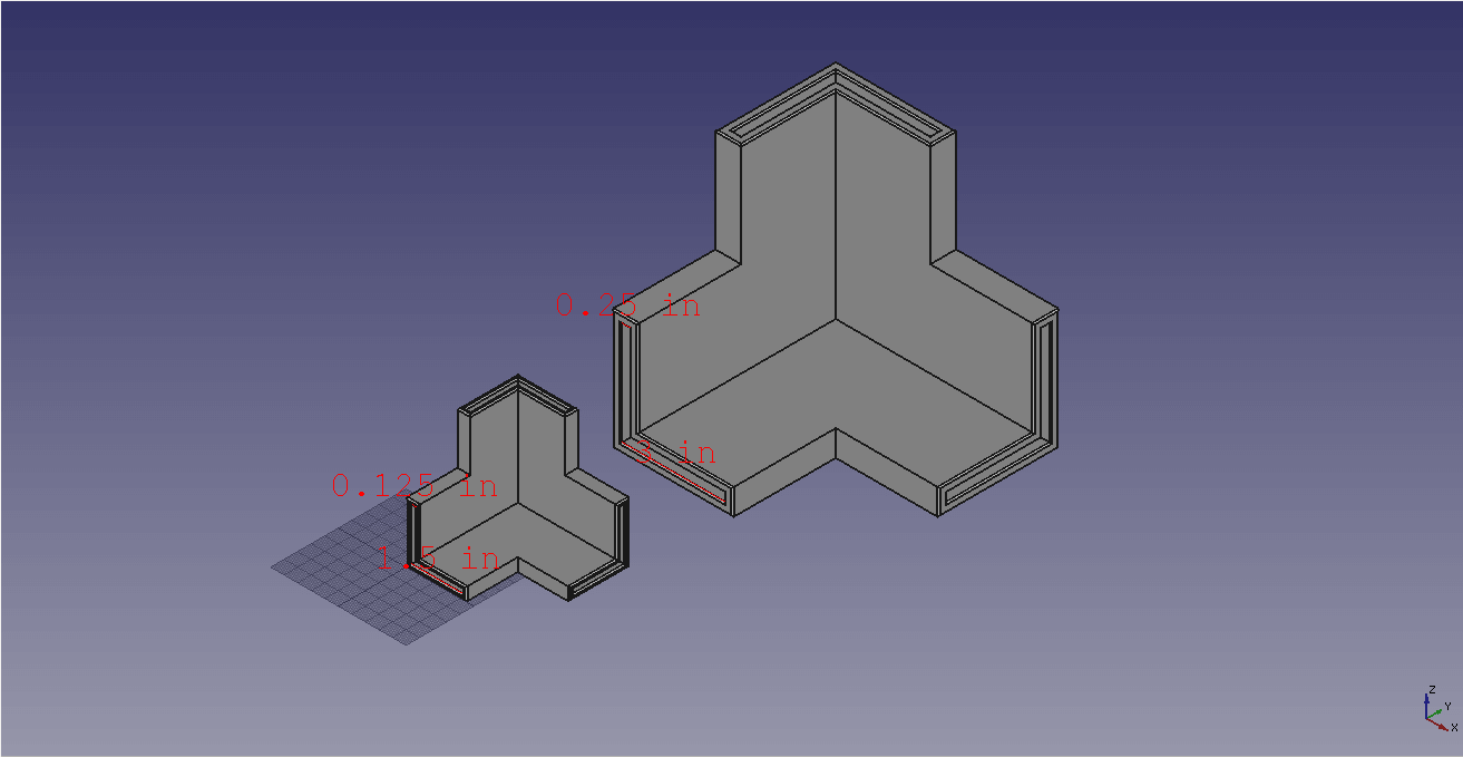
Angle Frame Connector with Different Sizes
Next Step
After the parts are designed, you can define the relationship between parts.